Do you wish to know how to use a scale ruler architect? You can learn to measure accurately and scale drawings like a pro with a ruler!
Whether you’re an architect or need to create accurate diagrams, this tool is essential.
Architects use scale rulers to determine and represent the measurements of immense structures, such as homes and buildings, and smaller objects, such as furniture, on properly sized pieces of paper.
In this blog post, we’ll guide you through using a scale ruler architect.
Architectural scale ruler
An architectural scale ruler is a specialized tool architects, engineers, and builders use to measure and draw accurate architectural drawings.
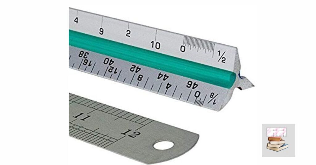
It is a triangular ruler that has three different scales on each edge. The most common scales are 1/4-inch, 1/8-inch, and 1/16-inch.
Each scale represents a different proportion of the actual size of the drawn object.
For example, if a wall is 10 feet tall, it would be defined on the drawing as 2.5 inches using a 1/4-inch scale.
Using an architectural scale ruler can be daunting initially, but it becomes second nature with practice.
It is an essential tool for anyone in the design and construction industry. Different architectural scale rulers, including plastic, metal, and wooden versions, are available.
It is critical to find the best ruler for your requirements and maintain it to guarantee correctness. With an excellent architectural scale ruler, you can create precise and detailed drawings that will help bring your design ideas to life.
Reading construction plans ruler architects.
Construction plans are typically drawn to scale, and architects and builders often use rulers to measure and mark dimensions.
Using the ruler, they can ensure that the measurements are accurate and that the finished building meets the intended specifications.
Understanding how to read construction plans and using a ruler to ensure the building is built to the necessary standards is essential.
Five Beginner Steps of ruler reading construction plans
- Familiarize yourself with the scale: The first step in reading construction plans is to familiarize yourself with the scale of the plan.
This is typically found in the legend and is used to convert distances on the plan to real-world measurements.
- Identify the orientation: Determine the direction of the plan, which North typically indicates.
- Locate the area of interest: Identify the specific area of interest on the plan, such as a room, floor, or building section.
- Measure distances: Use a ruler or measuring tape to measure the distances between different objects or features on the plan. Make sure to convert the measurements to real-world distances using the scale.
- Record measurements: Record the measures you have taken on a separate paper or notebook to reference them later. This will also help you keep track of your progress and ensure you accurately interpret the plan.
What exactly is an architect’s scale ruler?
An architect’s scale ruler is specialized ruler architects, and designers use to measure and draw scaled drawings of buildings and other structures.
It typically has three different scales, each marked with a different measurement ratio, allowing for accurate and precise measurements at different scales.
3 Common mistakes to avoid when using an architectural scale ruler
- Using the wrong scale: Make sure to match the scale on the ruler to the scale of the drawing or blueprint you are working with. Using the right scale can result in correct measurements and ultimately lead to errors in your project.
- Misreading the measurements: Architect scale rulers have multiple scales, so reading the correct scale and measure is essential. Be sure to pay attention to the number and unit of measurement (e.g., inches, feet, meters) you are using.
Failing to align the ruler properly: When using an architect scale ruler, be sure to align the “0” mark with the starting point of your measurement. You must do so to avoid inaccurate measurements and mistakes in your project.
How does a scale ruler work?
A scale ruler is specialized in technical drawing and architecture to measure and draw scaled-down versions of real-life objects.
It converts real-life measurements into a smaller scale that fits on the paper. The ruler is marked with various scales, such as 1:50 or 1:100, that indicate how many units on the ruler represent a certain number of units in the real world.
This allows the user to draw objects to scale accurately.
The most common scales are 1/2, 1/4, and 1/16. These are fractions of an inch that equate to feet in full-scale proportions.
To read a blueprint using a scale ruler, identify the suitable scale and then align the zero point with the start of the length to be measured.
The distance is measured in feet if it falls precisely on a line drawn with a ruler. As most scale rulers have two scales per side for best efficiency, ensure the correct markings are read.
If the measured distance does not fall precisely on a line, the actual length will be the number of feet matching the closest line crossed plus a specific number of inches.
How do you read an architectural scale bar?
To read an architectural scale bar, you should identify the unit of measurement (usually inches or feet) and find the corresponding measurement on the scale bar.
Then, use the scale to convert the distance on the drawing to its actual size. For example, if the scale is 1/4 inch = 1 foot, a line on the drawing measuring 2 inches would represent a distance of 8 feet in real life.
A scale bar is a linear graphic split into equal segments used to measure distances on drawings and maps prepared to a particular scale but only sometimes printed to that scale.
Many drawings, particularly in the design, architectural, and engineering industries, are printed precisely and may be measured using a scale rule.
However, including a scale bar ensures that the image may be measured with a standard ruler and any other well-proportioned item, like a credit card or coin.
Maps occur in various forms and sizes owing to the enormous regions shown and seldom reflect a standard drawing scale.
As a result, a scale bar is the only method to measure distance precisely.
Why are they significant?
Aside from making the map and drawing simpler to read, a scale bar eliminates the requirement for the drawing or map to be printed to a specific size.
This is due to the scale bar maintaining proportion to the drawing’s topic regardless of how large or tiny the image grows.
This is especially handy when measuring using a digital screen or mobile device when there isn’t a plotter nearby to print the needed paper size.
How do you scale architectural drawings?
Scale drawings are created. This implies that common fractions are utilized to represent the actual size of the drawn item and the measurements shown on the diagram.
Architectural drawings are created at sizes smaller than the actual size.
Floor plans, for example, are sometimes made at 1/50th (1 to 50) or 1/100th (1 to 100) of their proper size.
On the other hand, site plans are often drawn on a 1/200th (1 to 200) or even 1/500th (1 to 500) scale.
The symbol 1:100 indicates a scale of 1 to 100 on a drawing. This may be translated as follows: 1 centimeter (0.01 meter) measured using a ruler on the plan must be multiplied by 100 to produce the actual size of 1 meter.
So, if you measured a wall length as 1 centimeter on a 1:200 scale plan, the proper length of the wall would be 2 meters.
Mechanical drawings are often drawn to scale (1 to 1) or even more extensive (2 to 1). As a result, the image depicts these scales as 1:1 and 2:1.
The scale is displayed on the artwork, generally in the illustration’s title block. For example, various sections of a photograph may be at different scales. This will be shown next to each artwork.
You must understand the scale and be able to translate measurements from a sketch to actual size.
If the precise dimensions are not visible on the plan from the scale, you may figure out the measurements using a ruler.
For example, if you needed to run a conduit diagonally beneath, The size of the slab of concrete for a structure might be calculated necessarily by measuring from the plan.
Scales for Drawing (How to Read Scales including Metric Scales)
You must be able to read architectural and engineering drawing scales.
This part will teach you the following.
- How to Interpret an Architectural Scale (mostly used for buildings in the U.S.). 14 = 10 (148 size) and 18 = 10 (196 size)) architect scales
How to Read an Engineers Scale (Used primarily for road and topographical measurements) Engineer
- scales of measurement, such as 1 = 10′ or 1 = 50′, are used to measure distances and angles.
- How to Interpret a Metric Scale (primarily used for buildings in other parts of the world)
- How to calculate the scale of a drawing when the scale is not specified
Because drawing a structure to scale is impractical, different ratios indicate the actual building size.
On the other hand, the scale is a quick way to measure marked items, such as the length of ducts, pipelines, and electrical conduits.
The scale is often displayed in the bottom right-hand corner of the illustration or under the page title.
As they might be on floor plans, elevation plans, section views, and details, several distinct scales are often utilized in the same visuals.
How do architects convert scales?
The scale enables us to comprehend the relationship between the size of natural items and their representation in architectural drawings.
Consequently, the scale assists architects in correctly representing the inside and outside of a structure in smaller and more practical proportions than may describe on paper.
The architectural scale converter on our website may be used for various purposes. It may assist you with calculations for creating floor plans, sectional views, location plans, or building specifications, for example.
What is the purpose of an architectural scale calculator?
The architectural scale 1/4 = 1′-0 is used to sketch buildings and structures.
Because this scale compresses everything, if something in the actual world has a length of 1 foot, it will only have 1/4 inch in the architectural sketch.
The scale has three x values. 1.) Drawing length 2.) Colon “: “or equals “= “3.) Actual object length If you choose a 1:10 scale, 1 (unit) in the design equals 10 (units) in real life.
Example of a calculation:
1: 10
100 cm: 10
50/100 = win rate
10 cm as a result
Example of a calculation:
1 foot Equals 1/4 inch
16 x 1/4 inches equals 16 x 1 foot
16 feet = 4 inches
How do you read architectural rulers?
Reading an architectural ruler is simple if you understand why it differs from a regular ruler.
This is because architects work with reduced-scale drawings or blueprints. In other words, one foot is reduced to 1/4 inch for the picture to fit on the page.
An architect uses the 1/4-inch calibrated part of his ruler to ascertain the exact measurement.
Step 1
With the architectural ruler, lay down the blueprint or design you wish to read.
Step 2
Find the scale on your design or plan. This is usually located towards the bottom left of the page.
Step 3
Locate the equivalent scale, i.e., 1/4, on the architectural ruler “= 1′ (one-fourth inch equals one foot).
Step 4
Align the ruler’s edge (the side with the “1/4” mark at the end) with the item to be measured.
Step 5
Put a 0 in front of your expression to indicate that you wish to measure and write down the final measurement. For example, the “2” on the 1/4″ ruler signifies two feet inaccurate height but is only equal to 1/2,” or 2 x 1/4 on paper.”
How to Interpret an E-Scale Ruler
The typical individual may be confused while reading an E-scale, an Engineering scale, or a tri-scale.
It is simple to make a measurement error with three independent rulers, each with up to four unique ranks.
However, once you understand why and how the ruler is built up the way it is, your E-scale becomes an essential tool for deciphering engineering and architectural designs.
Because full-scale drawings would be too large, they are scaled down and translated using E-scales.
Locate the key on your diagram that provides the drawing’s scale. This material should be categorized as “legend.”
Determine if the design is architectural or engineering, and then choose the proper E-scale.
Engineering scales should have scales of 1:20, 1:25, 1:50, 1:75, 1:100, and 1:125 and be read from left to right.
Architectural scales are often labeled with 3/32, 3/16, 1/8, 1/4, 3/8, 1/2, 3/4, 1, 1-1/2, 3, and 16 scales and may be read left to right and right to left.
Set the ruler’s scale to match the scale of the drawing. Engineering scales, for example, should match engineering drawings, while architectural scales should match architectural drawings.
Check that the image was printed appropriately by setting the appropriate scale on the drawing’s scale.
These two should complement each other.
Place the proper scale at the beginning of the line, matched to the 0 (zero) on the scale, and take a reading from the ruler where the line finishes.
If the scale on the sketch indicates that 1/8 inch equals 1 foot, use the 1/8 ruler on your architect scale.
A line measured to the 32 mark on the 1/8 scale equals a length of 32 feet. If you unintentionally choose the 1/4 ranking, the same line would incorrectly represent a 16-foot distance.